 |
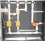
Pre-assembled, patented, TRICOIL® pump and valve assemblies. |

TRICOIL®Pump
and Valve Assemblies: The TRICOIL®
Pump and Valve Assemblies are pre-engineered to satisfy a majority
of applications. There are eight standard variations of the Pump
and Valve Packages. Other arrangements can be accommodated as specials.
|
Series |
Description |
|
TP |
TRICOIL® Pre-assembled Pump and Valve Packages: TRICOIL® Pumps, Valves and other components are pre-assembled in insulated cabinets and delivered to the job site ready for final installation in the piping system |
Hand indicates
the side of the assembly that the heating hot water connections
are on.
Type/Description
|
TP-A
 |
Single pump and one 3-way control valve. Recuperative water flow is constant. Hot water flow rate is variable. Typically used with local hot water heat source where pressure for hot water flow is provided by the TRICOIL® pump. |
|
TP-B
 |
Single pump and one 2-way control valve. Recuperative flow is constant. Hot water flow is variable. Typically used with central heating hot water plants which have there own variable volume pumping systems. The TRICOIL® pump does not provide pressure differential for hot water flow. |
|
TP-C
 |
Single pump and one 3-way control valve. Recuperative flow is constant. Hot water flow is constant. Typically used with central heating plants which have there own constant volume pumping system. TRICOIL® pump does not provide pressure differential for hot water flow. |
|
TP-D
 |
Two pumps and one 3-way control valve. Recuperative flow is constant. Hot water flow is constant. Typically used with local heating plants that require more pump head than is available from the recuperative loop pump. |
|
TP-E
 |
Single
pump and two 3-way control valves. Recuperative water flow
is variable through the reheat coil. Hot water flow rate is
variable. Typically used with local hot water heat source
where pressure for hot water flow is provided by the TRICOIL®
pump.
|
|
TP-F
 |
Single
pump, one 3-way control valve, and one 2-way control valve.
Recuperative water flow is variable through the reheat coil.
Hot water flow is variable. Typically used with central heating
plants which have there own variable volume pumping system.
The TRICOIL® pump does not provide pressure differential
for hot water flow.
|
|
TP-G
 |
Single
pump and one 3-way control valve. Recuperative water flow
is variable through the reheat coil. Hot water flow is constant.
Typically used with central heating plants which have there
own constant volume pumping system. TRICOIL® pump does
not provide pressure differential for hot water flow.
|
|
TP-H
 |
Two
pumps and two 3-way control valves. Recuperative water flow
is variable through the reheat coil. Hot water flow is constant.
Typically used with local heating plants that require more
pump head than is available from the recuperative loop pump.
|
|
Table
1: TRICOIL® Pump and Valve Assemblies:
|
||||||
|
Size
|
Air
Volume
|
Water
Data
|
Pump
Motor Horsepower
|
|||
|
CFM,
CAV
|
CFM,
VAV
|
Recuperative
Loop
|
Heating
Loop
|
|||
|
GPM
(1)
|
Loop "A"
|
Loop
"B" Select One
|
||||
|
02
|
925
|
1320
|
2.0
|
½
|
½
|
1/12
|
|
06
|
2780
|
3970
|
6.0
|
¾
|
½,
¾
|
1/6
|
|
12
|
5560
|
7940
|
12.0
|
1
|
½,
¾
|
1/6
|
|
14
|
7410
|
10580
|
16
|
1¼
|
½,
¾, 1
|
1/6
|
|
21
|
10185
|
14550
|
22
|
1½
|
½,
¾, 1, 1¼
|
1/6
|
|
30
|
16670
|
23810
|
36
|
2
|
½,
¾, 1, 1¼,1½
|
2
at 1/6
|
Available Pressure for Various Assembly Types: The different assembly types have different pressure available for the precooling and reheat water side pressure drop. |
Table 2:
|
Size
|
Pressure
Drop Available for Coils Ft.WC (1)
|
Add
to Available Pressure when Recuperative Loop Flow Control
Valve is not used. Ft WC
|
||
|
Type
A, F, G, H
|
Type
B, C, D
|
Type
E
|
||
|
02
|
5.1
|
7.4
|
2.8
|
2.3
|
|
06
|
7.9
|
10.2
|
5.6
|
4.6
|
|
12
|
6.5
|
8.8
|
4.2
|
2.3
|
|
14
|
7.0
|
10.0
|
4.0
|
4.6
|
|
21
|
4.9
|
7.4
|
2.3
|
4.6
|
|
30
|
4.2
|
7.5
|
2.9
|
9.3
|
-
The indicated pressure drop is for both the precooling and reheat coils piped in series taking into account 100 equivalent feet of pipe at the maximum flow rate.
|
TRICOIL® Pump Package Selection Procedures STEP 1 CALCULATE RECUPERATIVE WATER FLOW RATE, GPM. The recuperative water flow rate is proportional to the supply air flow rate for the majority of applications. Use standard engineering cooling load calculations to determine the supply air volume required. For Constant Air Volume (CAV) systems, multiply the supply air volume times the conversion factor, 0.00216 GPM/CFM, to determine the required recuperative water flow rate. For Variable Air Volume (VAV) systems multiply the supply air volume by 0.7 (for part load selection) then multiple by 0.00216.
STEP 2 SELECT PUMP/VALVE ASSEMBLY SIZE. To select the Pump Package size match the recuperative flow rate calculated in STEP 1, above, to the Flow Rate Column in the Selection Table. If there is no exact match use the next higher GPM value. Read the size of the Pump/Valve assembly next to the Available Flow Column. Select the actual flow in the recuperative loop by using note 1. Round off the recuperative flow rate to the closest value found in note 1.
STEP 3 DETERMINE PRESSURE DROP AVAILABLE FOR COILS The pressure drop available for precooling and reheat coils is indicated in the "Available Pressure" Column of Table 1 when Type A assemblies are used. Refer to Table 2 when type B thru type H are used. STEP 4 SELECT HOT WATER FLOW RATE The hot water flow rate can be as high as the recuperative water flow rate. Flow control valves are also used in the heating hot water circuit to automatically balance to the specified hot water flow rate. The available water pipe connection sizes are indicated in Table 1 and the available flow rates are indicated in note 2. TYPICAL AIR HANDLING UNIT WITH TRICOIL® PACKAGE PUMP AND VALVE ASSEMBLY
|

|
TYPICAL
TRICOIL PUMP/VALVE PACKAGE SCHEDULE
|
||||||||
|
TAG
|
Model
|
PUMP
DATA
|
PIPE
SIZE
|
|||||
|
Pipe
"A"
|
Pipe
"B"
|
Pipe
"C"
|
||||||
|
Size
|
HP
(120v/60hz/ 1phase) |
"A",
Inch Dia
|
GPM
|
"B"
Inch Dia.
|
GPM
|
"C"
Inch Dia.
|
GPM
|
|
|
TC-1
|
TP-A-02
|
1/12
|
1/2
|
2.0
|
1/2
|
1.0
|
3/4
|
7.0
|
|
TC-2
|
TP-C-06
|
1/6
|
3/4
|
6.0
|
3/4
|
3.33
|
1-1/2
|
20
|
|
TC-3
|
TP-D-14
|
1/6
|
1-1/4
|
16
|
1
|
10
|
2
|
55
|
|
TC-4
|
TPA-30
|
2
at 1/6 each
|
2
|
36
|
1-1/4
|
18
|
3
|
120
|
SENSIBLE EQUIPMENT COMPANY, INC.
P.O. BOX 669, GOLDENROD, FLORIDA 32733
PH (407) 296-8068 FAX (407) 296-7420
EMAIL kle@tricoil.com