|
|
|
|
TRICOIL®
PUMP AND VALVE KITS FOR FIELD ASSEMBLY
Field Assembled, patented, TRICOIL® pump
and valve Kits. |
TRICOIL®
Pump and Valve Packages The TRICOIL® Pump and Valve Packages
are pre-engineered to satisfy the majority of applications. There
are eight standard variations of the Pump and Valve Packages contained
in here. Other arrangements can be accommodated as specials.
| Series |
Description |
| TK |
Kits
are engineered to for field assembled applications by the installing
contractor. Pumps, Valves and other components are delivered
to the job site for installation in the piping system |
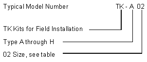
TRICOIL®
Pump and Valve Kits: There are EIGHT standard variations of the
Pump and Valve Packages. Kits offer the flexibility to accommodate
a broad variation of arrangements.
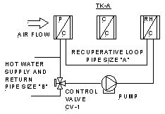
TKA
|
Single
pump and one 3-way control valve. Recuperative water flow is
constant. Hot water flow rate is variable. Typically used with
local hot water heat source where pressure for hot water flow
is provided by the TRICOIL® pump. |
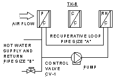
TKB
|
Single
pump and one 2-way control valve. Recuperative flow is constant.
Hot water flow is variable. Typically used with central heating
hot water plants which have there own variable volume pumping
systems. The TRICOIL® pump does not provide pressure differential
for hot water flow. |
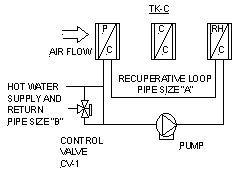
TKC
|
Single
pump and one 3-way control valve. Recuperative flow is constant.
Hot water flow is constant. Typically used with central heating
plants which have there own constant volume pumping system.
TRICOIL® pump does not provide pressure differential for
hot water flow. |
TKD
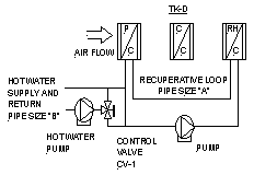
|
Two
pumps and one 3-way control valve. Recuperative flow is constant.
Hot water flow is constant. Typically used with local heating
plants that require more pump head than is available from the
recuperative loop pump. |
Each of the following
types of packages have a reheat coil by-pass valve. The by-pass
valve can be positioned for 100% water flow through the precooling
coil. This allows the precooling coil to be used as a preheat coil
for winter freeze protection of the primary coil. This is particularly
important for 100% outside air applications in cold climates.
TKE
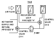
|
Single
pump and two 3-way control valves. Recuperative water flow
is variable through the reheat coil. Hot water flow rate is
variable. Typically used with local hot water heat source
where pressure for hot water flow is provided by the TRICOIL®
pump.
|
TKF
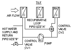
|
Single
pump, one 3-way control valve, and one 2-way control valve.
Recuperative water flow is variable through the reheat coil.
Hot water flow is variable. Typically used with central heating
plants which have there own variable volume pumping system.
The TRICOIL® pump does not provide pressure differential
for hot water flow.
|
TKG
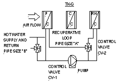
|
Single
pump and one 3-way control valve. Recuperative water flow
is variable through the reheat coil. Hot water flow is constant.
Typically used with central heating plants which have there
own constant volume pumping system. TRICOIL® pump does
not provide pressure differential for hot water flow.
|
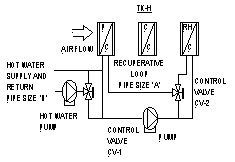
TKH
|
Two
pumps and two 3-way control valves. Recuperative water flow
is variable through the reheat coil. Hot water flow is constant.
Typically used with local heating plants that require more
pump head than is available from the recuperative loop pump.
|
|
Size
|
Air
Volume
|
Water
Data
|
Pump
Motor Horsepower
|
|
CAV
CFM
|
VAV
CFM
|
Recuperative
Loop
|
Heating
Loop
|
|
GPM
(1)
|
Loop
"A"
|
Loop
"B"
Select
|
|
02
|
925
|
1320
|
2.0
|
½
|
½
|
1/12
|
|
06
|
2780
|
3970
|
6.0
|
¾
|
½,
¾
|
1/6
|
|
12
|
5560
|
7940
|
12.0
|
1
|
½,
¾
|
1/6
|
|
14
|
7410
|
10580
|
16
|
1¼
|
½,
¾, 1
|
1/6
|
|
21
|
10185
|
14550
|
22
|
1½
|
½,
¾, 1, 1¼
|
1/6
|
|
30
|
15740
|
22490
|
34
|
1½
|
½,
¾, 1, 1¼, 1½
|
1/2
|
|
50
|
27780
|
39685
|
60
|
2
|
½,
¾, 1, 1¼, 1½
|
1.0
|
|
91
|
46300
|
66140
|
100
|
2½
|
½,
¾, 1, 1¼, 1½
|
1.5
|
1. The water flow rates
indicated are maximum for the indicated model number. The actual
flow is determined by the size of the flow control valve used in
the assembly. Available flow rates for each size are as indicated
below:
Size 02 GPM = 0.33, 0.5, 0.67, 1.0, 1.33, 1.67, or 2.0
Size 06 GPM = 2.33, 2.5, 2.67, 3.0, 3.33, 3.5, 4.0, 4.67, 5.0, or
6.0
Size 12 GPM = 6.67, 7.33, 8.0, 8.67, 9.33, 10.0, 10.67, 11.33, or
12.0
Size 14 GPM = 13.0, 13.33, 14.0, 14.67, 15.0, or 16.0
Size 21 GPM = 17.0, 18.0, 19.0, 20.0, 21.0, or 22.0
Size 30 GPM = 24.0, 26.0, 28.0, 30.0, 32.0, or 34.0
Size 50 GPM = 36.0 thru 60 at 2.0 increments
Size 91 GPM = 63.33 thru 100 at 3.33 increments
2. Specify
hot water connection size. The hot water flow rate can be no greater
than the recuperative water flow rate. The available hot water flow
for each connection size is as follows:
½” Diameter GPM = 0.33, 0.5, 0.67, 1.0, 1.33, or 1.67
¾” Diameter GPM = 2.0, 2.33, 2.67, 3.33, 4.0, 4.67, 5.33, or 6.0
1” Diameter GPM = 6.67, 7.33, 8.0, 8.67, 9.33, 10.0, 10.67, 11.33,
or 12.0
1¼” Diameter GPM = 13.0, 13.33, 14.0, 14.67, 15.0, 16.0, 17.0, 18.0,
19.0, 20.0, 21.0, or 22.0
1½” Diameter GPM = 24.0, 26.0, 28.0, 30.0, 32.0, 34.0, or 36.0
3. The pressure
available is the total pressure for two coils piped in series flow.
The pressure available has been adjusted to account for a maximum
of 100 equivalent feet of pipe at the maximum water flow rate for
pipe and fittings external to the pump and valve assembly.
4. Maximum
Air Volume for Variable Air Volume (VAV) Systems is typically 70%
greater than for Constant Air Volume (CAV) Systems.
5. Motor
electrical data is 120 volts, 60 Hertz, single phase for all 1/6
HP motors. Specify volts/phase hertz for larger motors.

|
